 |


Overview
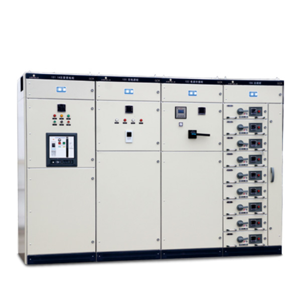
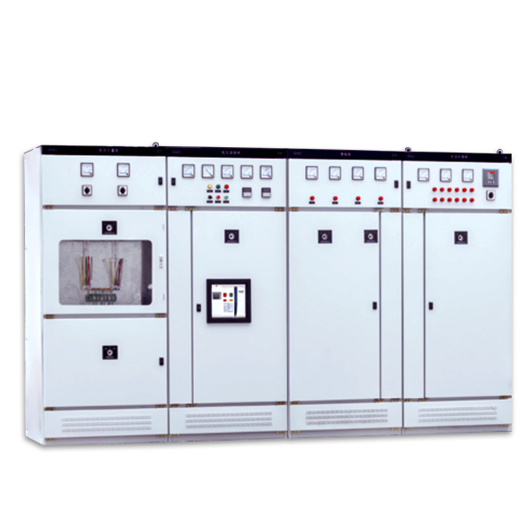
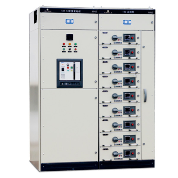
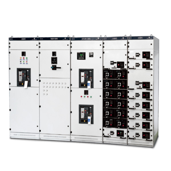
GCS low-voltage withdrawable switchgear is suitable for power distribution systems in power plants, petroleum, chemical, metallurgy, textile, high-rise buildings and other industries. In places with high degree of automation, such as large power plants and petrochemical systems, requiring interface with a computer, it is a power generation and power supply system with a three-phase AC frequency of 50 (60) Hz, rated operating voltages of 400 V and 660 V, and rated current of 5000 A or less Low-voltage power distribution equipment used in power distribution, centralized control of motors, and reactive power compensation.
The design of the device meets the following standards: IEC439-1 “Low-voltage switchgear and control equipment” GB7251 “Low-voltage switchgear”.
Model meaning

Normal operating conditions
♦ The ambient air temperature is not higher than +40℃, not lower than -5℃, and the average temperature within 24 hours must not be higher than +35℃. When it exceeds, it needs to be derated according to the actual situation;
♦ For indoor use, the altitude of the place of use must not exceed 2000m;
♦ The relative humidity of the surrounding air does not exceed 50% when the maximum temperature is +40°C, and a larger relative humidity is allowed at lower temperatures, such as 90% at +20°C. It should be considered that accidents may occur due to temperature changes The effect of condensation;
♦ When the device is installed, the inclination from the vertical plane does not exceed 5°, and the entire group of cabinet rows is relatively flat (in line with GBJ232-82 standard);
♦ The device should be installed in a place where there is no severe vibration and shock, and it is not enough to subject the electrical components to no corrosion;
♦ When the user has special requirements, he can negotiate with the manufacturer to solve it.
Main technical parameters
Basic technical parameters are shown in table 1
Serial number | Name | Parameters | |
1 | rated voltage (V) for main circuit | Communication 400/660 | |
2 | Auxiliary circuit rated voltage | AC 220,380(400), DC 110,220 | |
3 | rated frequency (Hz) | 50(60) | |
4 | rated insulation voltage (V) | 660 | |
5 | Current rating (A) | Horizontal busbar | w 5000 |
rated current (A)(MCC) | Vertical busbar | 1000 | |
6 | Bus rated short-time withstand current (kA/1s) | 50,80 | |
7 | Bus rated peak tolerance current (kA/0.1s) | 105,176 | |
8 | Power frequency test voltage (V/min) | Main circuit | 2500 |
Auxiliary circuit | 2000 | ||
9 | Bus bus | Three-phase four-wire system | A.B.C .PEN |
Three-phase five-wire system | A.B.C .P E.N | ||
10 | Protection level | IP30. IP40 | |
GCS low-voltage withdrawable switchgear is suitable for power distribution systems in power plants, petroleum, chemical, metallurgy, textile, high-rise buildings and other industries. In places with high degree of automation, such as large power plants and petrochemical systems, requiring interface with a computer, it is a power generation and power supply system with a three-phase AC frequency of 50 (60) Hz, rated operating voltages of 400 V and 660 V, and rated current of 5000 A or less Low-voltage power distribution equipment used in power distribution, centralized control of motors, and reactive power compensation.
The design of the device complies with the following standards: IEC439-1 “Low-voltage switchgear and control equipment” GB7251 “Low-voltage switchgear”.
♦ Main circuit scheme
The main circuit scheme of the GCS cabinet has a total of 32 groups and 118 specifications, excluding schemes and specifications derived from changes in control and protection of auxiliary circuits. Including the needs of power generation, power supply and other power users, the rated working current is 5000A, suitable for the selection of distribution transformers of 2500kVA and below. In addition, a capacitor compensation cabinet was designed to meet the needs of power supply to improve power factor, and a reactor cabinet was designed considering the needs of comprehensive investment.
♦ Auxiliary circuit scheme
GCS Auxiliary Circuit Atlas has 120 auxiliary circuit solutions, divided into two volumes. The first volume of the “AC Operation Part” is divided into 63 programs, and the next volume of the “DC Operation Part” has 57 programs. The auxiliary circuit scheme of the DC operation part is mainly used in the low-voltage plant (station) system of the power plant substation. It is suitable for the general control mode of low-voltage plant system of 200MW and below and 300MW and above capacity units, working (standby) power inlet, power feeder and motor feeder.
The auxiliary program of the AC operation part is mainly used for the low-voltage system of factories and mines and high-rise building substations. There are 6 combination schemes suitable for dual power supply operation control. It is also equipped with control circuits for operating electrical interlocking backup, automatic throwing and resetting, which can be directly used in engineering design.
The DC control power supply is DC 220V or 110V, and the AC control power supply is AC 380V or 220V, a complete cabinet composed of drawer units. The 220V control power source is derived from the public control power supply specially designed to control the power supply of the transformer in the cabinet. The public control power supply adopts the ungrounded mode to control the transformer, and the 24V power supply is reserved for the use of weak signal lights.
For the installation location of the watt-hour meter, the introduction method of the voltage signal and other installation and use requirements, please refer to the “Compiling Instructions” of the auxiliary circuit diagram.
♦ Main bus
In order to improve the dynamic thermal stability of the bus bar and improve the temperature rise of the contact surface, all the equipment adopts TMY-T2 series hard copper bars. The copper bars use full-length tin plating, and full-length silver-plated copper bus bars can also be used.
◇Horizontal bus and vertical bus are installed in the busbar isolation room inside the cabinet.
◇ Hard copper bar is used for neutral ground bus. Run through the horizontal neutral ground (PEN) or ground + neutral (PE+N).
♦ Selection of electrical components
The GCS cabinet mainly selects the advanced technology, stable performance index value is high, and adopts the imported electrical components that can be mass produced in China.
◇Main switch
For power inlet and feeder switches of 630A and above, the main selection is DW45 series, and DW48 series, AE series, 3WE or ME series can also be selected. Imported M series or F series can also be used when deemed necessary.
◇ The feeder and motor control switches below 630A mainly use TG series, CM1 series, NM series, CDM series, TG30 series and other plastic shell switches.
◇In order to improve the dynamic stability of the main circuit, the GCS series dedicated combined bus clamp and insulation support are designed, which are made of high-strength, flame-retardant synthetic materials with thermoplastic molding, high insulation strength, good self-extinguishing performance, and unique structure. .
◇In order to reduce the temperature rise of the spacer, connector and cable head of the functional unit, a special adapter for the GCS cabinet has been designed. The capacity of the adapter is large and the temperature rise is reduced.
◇If the design department selects new electrical components with better performance and more advanced technology according to the needs of users, because the GCS series cabinets have good versatility, it will not cause difficulties in manufacturing and installation due to updating electrical components.
| size(mm) | ||||
| Cabinet height (H) | 2200 | |||
| Cabinet width (D) | 400 | 600 | 800 | 1000 |
| Cabinet depth (W) | 800 1000 | 800 1000 | 600 800 1000 | 600 800 1000 |
| Serial number | Name | Tolerance (mm) | |
| 1 | Verticality | 3.3 | |
| 2 | Level | Two adjacent cabinet tops | 2 |
| Column top | 5 | ||
| 3 | Unevenness | Two adjacent cabinets | 1 |
| Row of cabinets | 5 | ||
| 4 | Cabinet indirect seam | 2 |
Installation and use
After the product arrives at the place of receipt, first of all, it should be checked whether the packaging is intact, and if any problem is found, the relevant department of the contract should be notified in time to make business records, analyze the reasons together, and obtain evidence and deal with it afterwards. For products that are not installed immediately, they should be placed in an appropriate place and properly stored according to the normal use conditions and the requirements for temporary storage of electrical equipment.
♦ The installation of the product should be carried out according to the installation diagram. The base channel steel and the bolts when bolting is used are prepared by the user. When the main busbar is connected, if the surface is uneven due to transportation, storage, etc., it needs to be smoothed before connecting and tightening.
♦ When the equipment is installed alone or in a row, the verticality, the unevenness of the cabinet surface and the deviation of the gap between the cabinets should meet the requirements of Table 3.
♦ Inspection and test before product put into operation after product installation
◇Check whether the cabinet finish paint or other covering materials (such as spray plastic) are damaged and whether the cabinet is dry and clean.
◇Whether the operating mechanism of electrical components is flexible, and there should be no stagnation or excessive operating force.
◇ Whether the on and off of the main electrical appliances are reliable and accurate.
◇Drawer or draw-out mechanism should be flexible, light, free of jamming and collision.
◇The center line of the dynamic and static contacts of the drawer or withdrawable structure should be consistent, and the contact should be tight. The insertion depth of the main and auxiliary contacts should meet the requirements. The mechanical interlocking or electrical interlocking device shall act correctly, and the locking or releasing shall be reliable.
◇The drawer with the same plan, second principle and same drawer size should be easily interchangeable without jamming or collision.
◇When replacing the fuse core, it should meet the requirements of engineering design.
◇The setting value of protection should be set correctly according to the actual load.
◇Measure the insulation resistance value with a 1000V megohmmeter not less than 10MΩ.
◇The connection of each bus bar should be good, and the installation of insulating supports, mounting parts and other accessories should be firm and reliable.
♦ Precautions for use
◇ The equipment is a low-voltage distribution cabinet that is not installed against the wall, is operated on the front, and is maintained on both sides. The maintenance channel and door of the cabinet must only be accessed or opened by qualified professionals for operation, inspection and maintenance.
◇After multiple opening and closing of air circuit breakers and molded case circuit breakers, especially after short circuit opening and closing, local contact burns and carbon materials will be generated, and the contact resistance will increase. Maintenance and repair.
◇After installation and maintenance, the isolation between the compartments and functional units must be strictly checked to ensure the good functional separation of the device and prevent the expansion of failures.
♦ Drawer operation
◇ Operation of 1/2 drawer
The operating mechanism of the drawer is composed of a rotating part, a rotating shaft, a lock catch, etc., and has functions of opening and closing, testing, isolation and locking of the switch. The operating mechanism is also equipped with a micro switch for electrical blocking.
Working position: the main switch is closed, the main circuit and the control circuit are connected, and the functional unit is locked.
Opening position: the main switch is open, the control circuit is connected, and the functional unit is locked.
Test position: The main switch is opened, the main circuit is disconnected, the control circuit is connected, and the functional unit is locked.
Isolation position: drawer draws out 30mm. The main and control circuits are isolated and disconnected, and the drawer is locked.
Pumping position: The main circuit and the control circuit are disconnected, and the drawer can be arbitrarily drawn out.
After the operating handle is pushed down 6mm, it can turn from the “opening position” (working position).
Working process: In the “pulling position“, the drawer can only be pushed or pulled. After turning 45° counterclockwise, the drawer can automatically reach the isolation position when pulled. Turn 45° clockwise to reach the “test position“. Then turn it 45° clockwise to reach the “breaking position” of the switch. Press the handle down 6mm and turn it clockwise 90°, the switch closes, if you need to back out, then reverse the operation in turn.
If necessary, a padlock can be added on the operating handle to open, test and isolate the main switch as a safety protection.
◊Operation of unit and above drawers
The operating mechanism of the drawer is composed of a rotating shaft, a cylindrical cam, a clutch tooth plate, a shaft pin compression spring, a shift fork and the like. The drawer can be inserted and pulled by turning the cylindrical cam by operating the handle and has the functions of opening, closing, testing, isolating and locking of the switch.
Working position: the main switch is closed, the main circuit and the control circuit are connected, and the functional unit is locked.
Opening position: the main switch is open, the control circuit is connected, and the functional unit is locked.
Test position: The main switch is opened, the main circuit is disconnected, the control circuit is connected, and the functional unit is locked.
Isolation position: drawer draws out 30mm. The main and control circuits are isolated and disconnected, and the drawer is locked.
Withdrawal position: The main circuit and the control circuit are disconnected, and the drawer can be arbitrarily drawn. After the operating handle is pushed down 9mm, it can be turned from “opening position” to “working position“.
Working process: At (drawing position), the drawer can only be screwed in or out. The operating handle rotates 30° clockwise to reach the “isolated position“, and then rotates clockwise 1/2 unit drawer to reach the test position. After continuing to turn clockwise by 30°, it reaches the “switch disconnection position“, press the handle down 9mm and turn it clockwise by 90°, the main switch is closed, if you need to exit, then operate in reverse.
If necessary, a padlock can be added on the operating handle to open, test and isolate the main switch as a safety protection.
♦ Unlocking mechanism
There is a red plastic button in the lower right corner of the drawer of unit 1 and above. This is the unlocking mechanism. When the operating mechanism is faulty, repaired or needs to be opened, put the operating handle in the “opening position“, press the red plastic button Can open the door.
Shape and installation dimensions

| Cabinet depth (W) | Cabinet width (D) | Cabinet height (H) |
| 6,008,001,000 | 8,001,000 | 2200 |
Factory information and accessories
♦ The manufacturer should provide the following documents and accessories when supplying
◇ Shipping list
◇ Product certificate and factory test report
◇ Instruction manual
◇ Relevant electrical drawings
◇ Main component manual
◇ Cabinet key, operating handle and spare parts specified in the contract.
download Google
♦ The user should provide:
◇ Main circuit power distribution system diagram and plane layout diagram, rated working voltage, rated working current, protection device setting current and necessary technical parameters.
◇ Indicate the cable specifications of the incoming and outgoing lines.
◇ The model, specification and quantity of the main electrical components in the switch cabinet.
◇ If there is a bus bridge or bus duct between switch cabinets or incoming cabinets, the specific requirements such as span and height from the ground shall be indicated.
◇ When the switch cabinet is used in special environmental conditions, it should be explained in detail when ordering.
◇ The color of the surface of the switch cabinet and other specific requirements.
Overview
GCS low-voltage withdrawable switchgear is suitable for power distribution systems in power plants, petroleum, chemical, metallurgy, textile, high-rise buildings and other industries. In places with high degree of automation, such as large power plants and petrochemical systems, requiring interface with a computer, it is a power generation and power supply system with a three-phase AC frequency of 50 (60) Hz, rated operating voltages of 400 V and 660 V, and rated current of 5000 A or less Low-voltage power distribution equipment used in power distribution, centralized control of motors, and reactive power compensation.
The design of the device meets the following standards: IEC439-1 “Low-voltage switchgear and control equipment” GB7251 “Low-voltage switchgear”.
Model meaning
Normal operating conditions
♦ The ambient air temperature is not higher than +40℃, not lower than -5℃, and the average temperature within 24 hours must not be higher than +35℃. When it exceeds, it needs to be derated according to the actual situation;
♦ For indoor use, the altitude of the place of use must not exceed 2000m;
♦ The relative humidity of the surrounding air does not exceed 50% when the maximum temperature is +40°C, and a larger relative humidity is allowed at lower temperatures, such as 90% at +20°C. It should be considered that accidents may occur due to temperature changes The effect of condensation;
♦ When the device is installed, the inclination from the vertical plane does not exceed 5°, and the entire group of cabinet rows is relatively flat (in line with GBJ232-82 standard);
♦ The device should be installed in a place where there is no severe vibration and shock, and it is not enough to subject the electrical components to no corrosion;
♦ When the user has special requirements, he can negotiate with the manufacturer to solve it.
Main technical parameters
Basic technical parameters are shown in table 1
Serial number | Name | Parameters | |
1 | rated voltage (V) for main circuit | Communication 400/660 | |
2 | Auxiliary circuit rated voltage | AC 220,380(400), DC 110,220 | |
3 | rated frequency (Hz) | 50(60) | |
4 | rated insulation voltage (V) | 660 | |
5 | Current rating (A) | Horizontal busbar | w 5000 |
rated current (A)(MCC) | Vertical busbar | 1000 | |
6 | Bus rated short-time withstand current (kA/1s) | 50,80 | |
7 | Bus rated peak tolerance current (kA/0.1s) | 105,176 | |
8 | Power frequency test voltage (V/min) | Main circuit | 2500 |
Auxiliary circuit | 2000 | ||
9 | Bus bus | Three-phase four-wire system | A.B.C .PEN |
Three-phase five-wire system | A.B.C .P E.N | ||
10 | Protection level | IP30. IP40 | |
GCS low-voltage withdrawable switchgear is suitable for power distribution systems in power plants, petroleum, chemical, metallurgy, textile, high-rise buildings and other industries. In places with high degree of automation, such as large power plants and petrochemical systems, requiring interface with a computer, it is a power generation and power supply system with a three-phase AC frequency of 50 (60) Hz, rated operating voltages of 400 V and 660 V, and rated current of 5000 A or less Low-voltage power distribution equipment used in power distribution, centralized control of motors, and reactive power compensation.
The design of the device complies with the following standards: IEC439-1 “Low-voltage switchgear and control equipment” GB7251 “Low-voltage switchgear”.
♦ Main circuit scheme
The main circuit scheme of the GCS cabinet has a total of 32 groups and 118 specifications, excluding schemes and specifications derived from changes in control and protection of auxiliary circuits. Including the needs of power generation, power supply and other power users, the rated working current is 5000A, suitable for the selection of distribution transformers of 2500kVA and below. In addition, a capacitor compensation cabinet was designed to meet the needs of power supply to improve power factor, and a reactor cabinet was designed considering the needs of comprehensive investment.
♦ Auxiliary circuit scheme
GCS Auxiliary Circuit Atlas has 120 auxiliary circuit solutions, divided into two volumes. The first volume of the “AC Operation Part” is divided into 63 programs, and the next volume of the “DC Operation Part” has 57 programs. The auxiliary circuit scheme of the DC operation part is mainly used in the low-voltage plant (station) system of the power plant substation. It is suitable for the general control mode of low-voltage plant system of 200MW and below and 300MW and above capacity units, working (standby) power inlet, power feeder and motor feeder.
The auxiliary program of the AC operation part is mainly used for the low-voltage system of factories and mines and high-rise building substations. There are 6 combination schemes suitable for dual power supply operation control. It is also equipped with control circuits for operating electrical interlocking backup, automatic throwing and resetting, which can be directly used in engineering design.
The DC control power supply is DC 220V or 110V, and the AC control power supply is AC 380V or 220V, a complete cabinet composed of drawer units. The 220V control power source is derived from the public control power supply specially designed to control the power supply of the transformer in the cabinet. The public control power supply adopts the ungrounded mode to control the transformer, and the 24V power supply is reserved for the use of weak signal lights.
For the installation location of the watt-hour meter, the introduction method of the voltage signal and other installation and use requirements, please refer to the “Compiling Instructions” of the auxiliary circuit diagram.
♦ Main bus
In order to improve the dynamic thermal stability of the bus bar and improve the temperature rise of the contact surface, all the equipment adopts TMY-T2 series hard copper bars. The copper bars use full-length tin plating, and full-length silver-plated copper bus bars can also be used.
◇Horizontal bus and vertical bus are installed in the busbar isolation room inside the cabinet.
◇ Hard copper bar is used for neutral ground bus. Run through the horizontal neutral ground (PEN) or ground + neutral (PE+N).
♦ Selection of electrical components
The GCS cabinet mainly selects the advanced technology, stable performance index value is high, and adopts the imported electrical components that can be mass produced in China.
◇Main switch
For power inlet and feeder switches of 630A and above, the main selection is DW45 series, and DW48 series, AE series, 3WE or ME series can also be selected. Imported M series or F series can also be used when deemed necessary.
◇ The feeder and motor control switches below 630A mainly use TG series, CM1 series, NM series, CDM series, TG30 series and other plastic shell switches.
◇In order to improve the dynamic stability of the main circuit, the GCS series dedicated combined bus clamp and insulation support are designed, which are made of high-strength, flame-retardant synthetic materials with thermoplastic molding, high insulation strength, good self-extinguishing performance, and unique structure. .
◇In order to reduce the temperature rise of the spacer, connector and cable head of the functional unit, a special adapter for the GCS cabinet has been designed. The capacity of the adapter is large and the temperature rise is reduced.
◇If the design department selects new electrical components with better performance and more advanced technology according to the needs of users, because the GCS series cabinets have good versatility, it will not cause difficulties in manufacturing and installation due to updating electrical components.
| size(mm) | ||||
| Cabinet height (H) | 2200 | |||
| Cabinet width (D) | 400 | 600 | 800 | 1000 |
| Cabinet depth (W) | 800 1000 | 800 1000 | 600 800 1000 | 600 800 1000 |
| Serial number | Name | Tolerance (mm) | |
| 1 | Verticality | 3.3 | |
| 2 | Level | Two adjacent cabinet tops | 2 |
| Column top | 5 | ||
| 3 | Unevenness | Two adjacent cabinets | 1 |
| Row of cabinets | 5 | ||
| 4 | Cabinet indirect seam | 2 |
Installation and use
After the product arrives at the place of receipt, first of all, it should be checked whether the packaging is intact, and if any problem is found, the relevant department of the contract should be notified in time to make business records, analyze the reasons together, and obtain evidence and deal with it afterwards. For products that are not installed immediately, they should be placed in an appropriate place and properly stored according to the normal use conditions and the requirements for temporary storage of electrical equipment.
♦ The installation of the product should be carried out according to the installation diagram. The base channel steel and the bolts when bolting is used are prepared by the user. When the main busbar is connected, if the surface is uneven due to transportation, storage, etc., it needs to be smoothed before connecting and tightening.
♦ When the equipment is installed alone or in a row, the verticality, the unevenness of the cabinet surface and the deviation of the gap between the cabinets should meet the requirements of Table 3.
♦ Inspection and test before product put into operation after product installation
◇Check whether the cabinet finish paint or other covering materials (such as spray plastic) are damaged and whether the cabinet is dry and clean.
◇Whether the operating mechanism of electrical components is flexible, and there should be no stagnation or excessive operating force.
◇ Whether the on and off of the main electrical appliances are reliable and accurate.
◇Drawer or draw-out mechanism should be flexible, light, free of jamming and collision.
◇The center line of the dynamic and static contacts of the drawer or withdrawable structure should be consistent, and the contact should be tight. The insertion depth of the main and auxiliary contacts should meet the requirements. The mechanical interlocking or electrical interlocking device shall act correctly, and the locking or releasing shall be reliable.
◇The drawer with the same plan, second principle and same drawer size should be easily interchangeable without jamming or collision.
◇When replacing the fuse core, it should meet the requirements of engineering design.
◇The setting value of protection should be set correctly according to the actual load.
◇Measure the insulation resistance value with a 1000V megohmmeter not less than 10MΩ.
◇The connection of each bus bar should be good, and the installation of insulating supports, mounting parts and other accessories should be firm and reliable.
♦ Precautions for use
◇ The equipment is a low-voltage distribution cabinet that is not installed against the wall, is operated on the front, and is maintained on both sides. The maintenance channel and door of the cabinet must only be accessed or opened by qualified professionals for operation, inspection and maintenance.
◇After multiple opening and closing of air circuit breakers and molded case circuit breakers, especially after short circuit opening and closing, local contact burns and carbon materials will be generated, and the contact resistance will increase. Maintenance and repair.
◇After installation and maintenance, the isolation between the compartments and functional units must be strictly checked to ensure the good functional separation of the device and prevent the expansion of failures.
♦ Drawer operation
◇ Operation of 1/2 drawer
The operating mechanism of the drawer is composed of a rotating part, a rotating shaft, a lock catch, etc., and has functions of opening and closing, testing, isolation and locking of the switch. The operating mechanism is also equipped with a micro switch for electrical blocking.
Working position: the main switch is closed, the main circuit and the control circuit are connected, and the functional unit is locked.
Opening position: the main switch is open, the control circuit is connected, and the functional unit is locked.
Test position: The main switch is opened, the main circuit is disconnected, the control circuit is connected, and the functional unit is locked.
Isolation position: drawer draws out 30mm. The main and control circuits are isolated and disconnected, and the drawer is locked.
Pumping position: The main circuit and the control circuit are disconnected, and the drawer can be arbitrarily drawn out.
After the operating handle is pushed down 6mm, it can turn from the “opening position” (working position).
Working process: In the “pulling position“, the drawer can only be pushed or pulled. After turning 45° counterclockwise, the drawer can automatically reach the isolation position when pulled. Turn 45° clockwise to reach the “test position“. Then turn it 45° clockwise to reach the “breaking position” of the switch. Press the handle down 6mm and turn it clockwise 90°, the switch closes, if you need to back out, then reverse the operation in turn.
If necessary, a padlock can be added on the operating handle to open, test and isolate the main switch as a safety protection.
◊Operation of unit and above drawers
The operating mechanism of the drawer is composed of a rotating shaft, a cylindrical cam, a clutch tooth plate, a shaft pin compression spring, a shift fork and the like. The drawer can be inserted and pulled by turning the cylindrical cam by operating the handle and has the functions of opening, closing, testing, isolating and locking of the switch.
Working position: the main switch is closed, the main circuit and the control circuit are connected, and the functional unit is locked.
Opening position: the main switch is open, the control circuit is connected, and the functional unit is locked.
Test position: The main switch is opened, the main circuit is disconnected, the control circuit is connected, and the functional unit is locked.
Isolation position: drawer draws out 30mm. The main and control circuits are isolated and disconnected, and the drawer is locked.
Withdrawal position: The main circuit and the control circuit are disconnected, and the drawer can be arbitrarily drawn. After the operating handle is pushed down 9mm, it can be turned from “opening position” to “working position“.
Working process: At (drawing position), the drawer can only be screwed in or out. The operating handle rotates 30° clockwise to reach the “isolated position“, and then rotates clockwise 1/2 unit drawer to reach the test position. After continuing to turn clockwise by 30°, it reaches the “switch disconnection position“, press the handle down 9mm and turn it clockwise by 90°, the main switch is closed, if you need to exit, then operate in reverse.
If necessary, a padlock can be added on the operating handle to open, test and isolate the main switch as a safety protection.
♦ Unlocking mechanism
There is a red plastic button in the lower right corner of the drawer of unit 1 and above. This is the unlocking mechanism. When the operating mechanism is faulty, repaired or needs to be opened, put the operating handle in the “opening position“, press the red plastic button Can open the door.
Shape and installation dimensions
| Cabinet depth (W) | Cabinet width (D) | Cabinet height (H) |
| 6,008,001,000 | 8,001,000 | 2200 |
Factory information and accessories
♦ The manufacturer should provide the following documents and accessories when supplying
◇ Shipping list
◇ Product certificate and factory test report
◇ Instruction manual
◇ Relevant electrical drawings
◇ Main component manual
◇ Cabinet key, operating handle and spare parts specified in the contract.
download Google
♦ The user should provide:
◇ Main circuit power distribution system diagram and plane layout diagram, rated working voltage, rated working current, protection device setting current and necessary technical parameters.
◇ Indicate the cable specifications of the incoming and outgoing lines.
◇ The model, specification and quantity of the main electrical components in the switch cabinet.
◇ If there is a bus bridge or bus duct between switch cabinets or incoming cabinets, the specific requirements such as span and height from the ground shall be indicated.
◇ When the switch cabinet is used in special environmental conditions, it should be explained in detail when ordering.
◇ The color of the surface of the switch cabinet and other specific requirements.